Precision silicone overmolding · drawing review → sampling → volume

Overmolding applications: RFID chips and LED modules

Two electronic product families show the same logic at work: an RFID chip has to be protected without losing read range, and an LED module has to be sealed against weather without losing light.

Two places where overmolding meets electronics

Encapsulating an electronic assembly in silicone is not only about water and dust. A chip, an antenna or an LED module sits inside a layer that absorbs impact, keeps moisture out and takes up thermal movement, while the part stays soft enough to wear on a wrist or to touch.

Both cases below come from product directions supplied by customers. What we take on is the overmolding and composite molding step: coverage area, wall thickness, gate position and surface finish are fixed from the chip package, the operating environment and the appearance requirement.

Dimensions, weights and temperature figures on this page come from the customer-supplied samples shown. They indicate a direction only; structure and parameters for a project are confirmed after a drawing or sample is reviewed.
Silicone wristband with an overmolded RFID chip
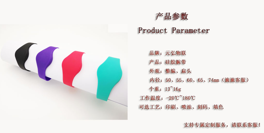
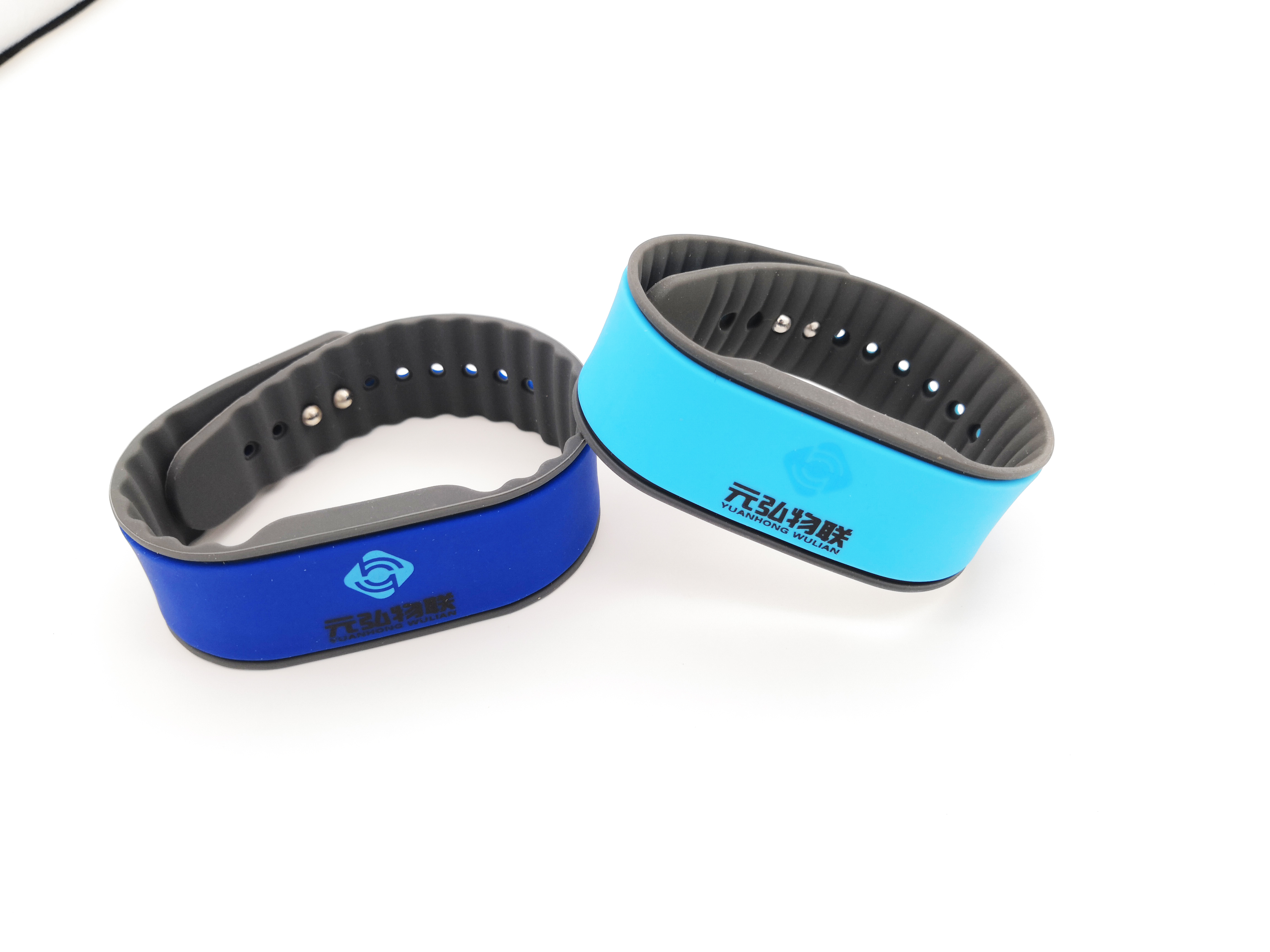
A silicone wristband with an RFID chip inside: colour and print are added around the encapsulated chip and antenna.

Case direction one

Silicone over RFID chips: wristbands, rings and tags

The same chip becomes a wristband, a ring or a tag depending on how the part is loaded and worn, and each shape leaves a different margin for coverage thickness.

Silicone RFID wristband used for gym access and events
Wristband

Silicone RFID wristband

Straight and flat-head band types, with the chip and antenna encapsulated inside the band for access control, membership, events and gyms.

  • Inner diameter, clasp position and how tight it sits
  • How chip offset affects reading
  • Printing, spray coating and laser marking
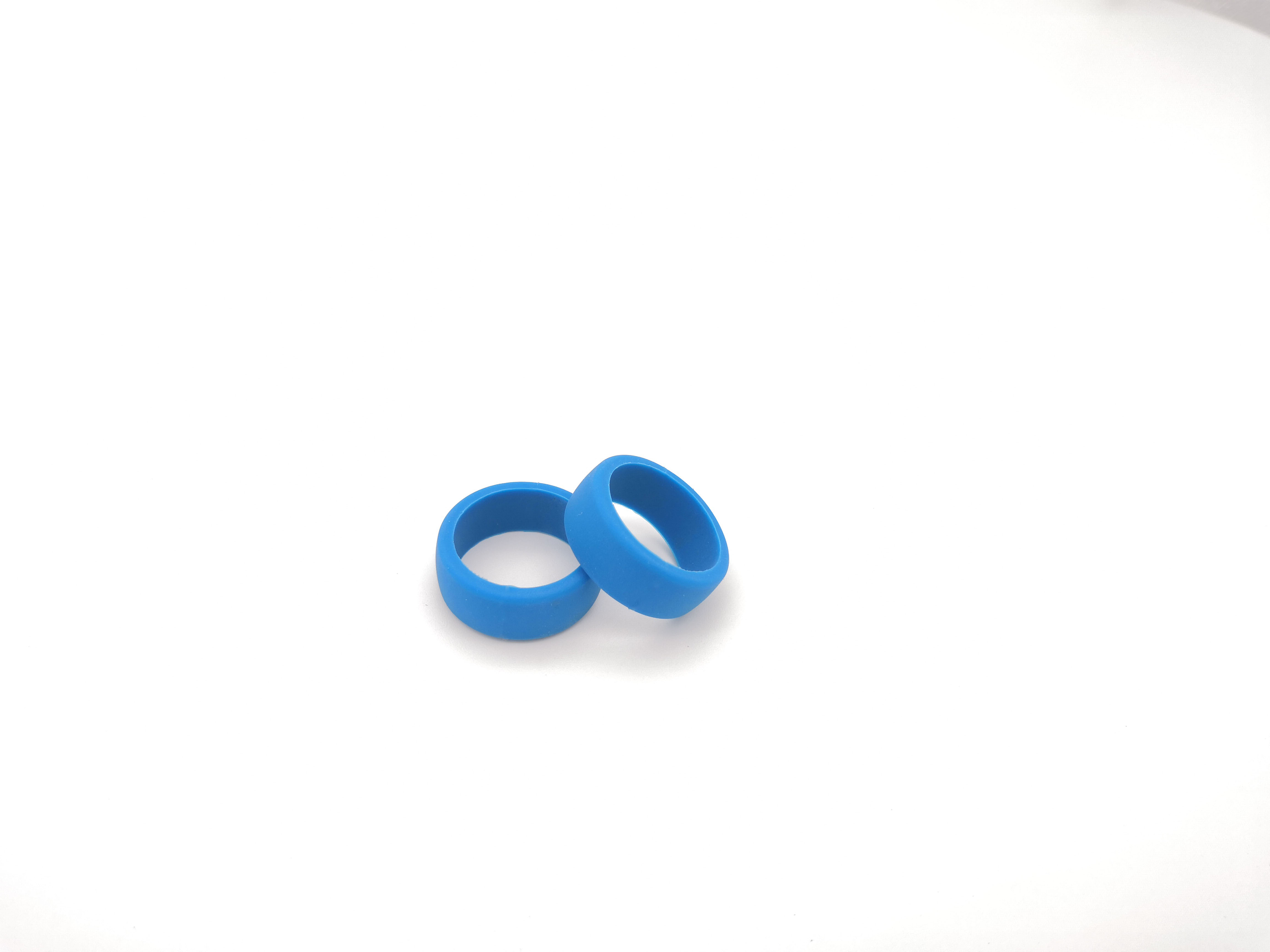
Silicone NFC ring with an encapsulated chip
NFC ring

Silicone NFC ring

A small part with a tight bend radius: the chip and coil have to be moulded inside a very thin layer, which makes shot weight the hardest thing to control.

  • Coverage thickness against comfort on the finger
  • Whether coil stress shortens the read distance
  • Colour uniformity and parting line position
Custom silicone wristband in two colours
Custom band

Custom band shapes and colours

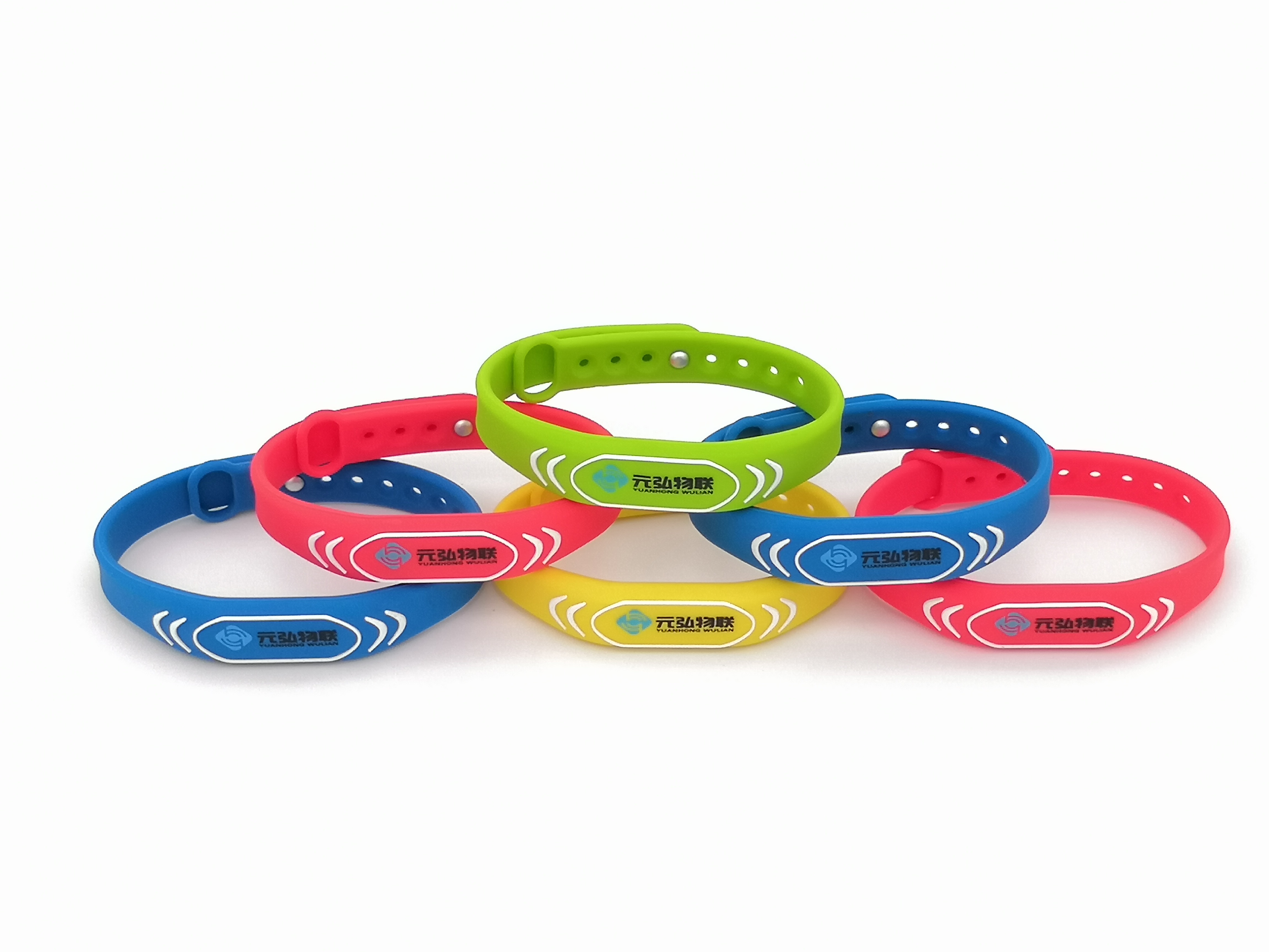
Band width, length and colour follow the project, and different colours can be combined on one band.

  • Split lines when two or more colours meet
  • Surface texture and hand feel on the band body
  • Colour consistency checks across a batch
Silicone laundry tag used for textile tracking
Laundry tag

Silicone laundry tag

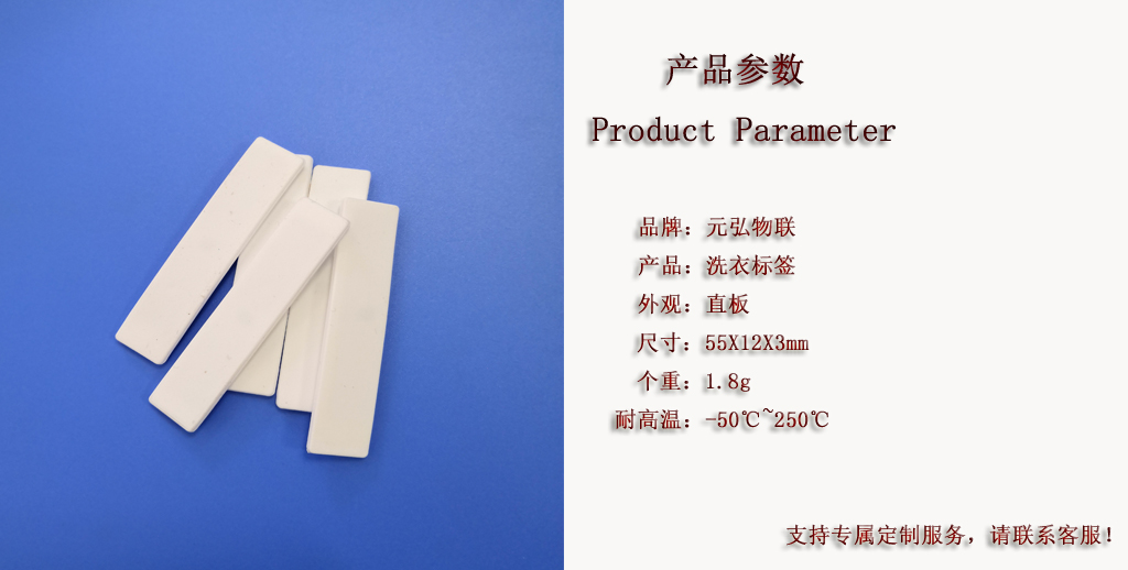
Used on linen, workwear and rental textiles, the tag meets water, detergent and heat on every wash, so the coverage layer has to resist hydrolysis as well as temperature.

  • Flat body, commonly 55 x 12 x 3 mm at about 1.8 g
  • Sample marked for -50 to 250 degrees C
  • Integrity after repeated bending and drum washing
Silicone band with an encapsulated payment card chip
Card and payment

Cards and payment chips

A card chip is sealed into a flexible silicone band so the part can be worn on the wrist while contactless payment still works.

  • Positioning accuracy of the chip and antenna coil
  • Function kept while the part is bent
  • Printing and wear resistance on the card face
Precision silicone overmolded parts, brand visual
Pet and cold chain

Pet tags and cold-chain labels

Pet tags stay exposed, taking abrasion and temperature swings; cold-chain labels have to stay readable at low temperature and through frost.

  • Hole and corner structure where the tag is loaded
  • Hardness change at low temperature
  • Wear and cold resistance of the marking

Wristband sample figures

Band type
Straight or flat head (project dependent)
Inner diameter
50 / 55 / 60 / 65 / 74 mm
Weight
about 13 to 16 g
Operating temperature
-20 to 180 degrees C
Optional processes
Printing, spray coating, laser marking, colour filling

Tag sample figures

Body
Flat (laundry tag)
Size
55 x 12 x 3 mm
Weight
about 1.8 g
Heat resistance
-50 to 250 degrees C
Customisation
Size, temperature requirement and marking confirmed per project

What decides chip overmolding

Chip movement, temperature and fill force

The chip is rigid; the silicone flows around it under pressure. Whether the part can be made comes down to controlling three things at the same time.

Position: within 0.5 mm per side

During clamping and filling the chip is pushed in six directions. Our positioning method holds displacement to within 0.5 mm per side, so the chip ends up where the design puts it inside the coverage layer.

Temperature: the chip survives the cure

Molding temperature is limited by what the chip can take. The target is a fully cured silicone without damage to the internal structure, so the part still works after encapsulation and keeps working through repeated use.

Runner: no strong squeeze on the chip

Compound entering the cavity drags the chip with it. Runner and gate position are laid out around the chip and antenna so the fill stays steady and the chip is not pushed off centre or its solder joints damaged.

How these three interact, and what sampling has to prove, is described in silicone overmolding failure: 8 modes and a bonding matrix.

Case direction two

Silicone over LED modules: precision liquid encapsulation

The encapsulation layer on an outdoor LED module sits in UV, rain and thermal cycling for years, which makes it one of the parts that decide how long the screen lasts.

The usual route is potting the LEDs or the module with a resin. The overmolding route covers the module surface directly with precision liquid silicone, forming an elastic light-transmitting layer in place of the resin encapsulation.

For outdoor use, what has to be checked is how the layer behaves under UV and thermal shock, how brightness and viewing angle change after coverage, whether the water and dust path across the module is continuous, and how the module can be reworked later.

What to confirmWhy it has to be settled before tooling
Coverage method and thickness Liquid silicone flow and cavity structure decide whether the layer is even; thickness drives both light transmission and protection.
LED and solder joint protection A gate placed straight onto a component will push it off or damage the joint while the cavity fills.
Outdoor weathering UV, rain and thermal cycling age the layer; compound and hardness follow the actual climate the product ships into.
Water and sealing path Module frame, connectors and cable exits are where water gets in, so the coverage layer has to continue the seal across them.
Rework and repair How the module comes apart has to be considered at design stage, or a single failed LED scraps the whole board.
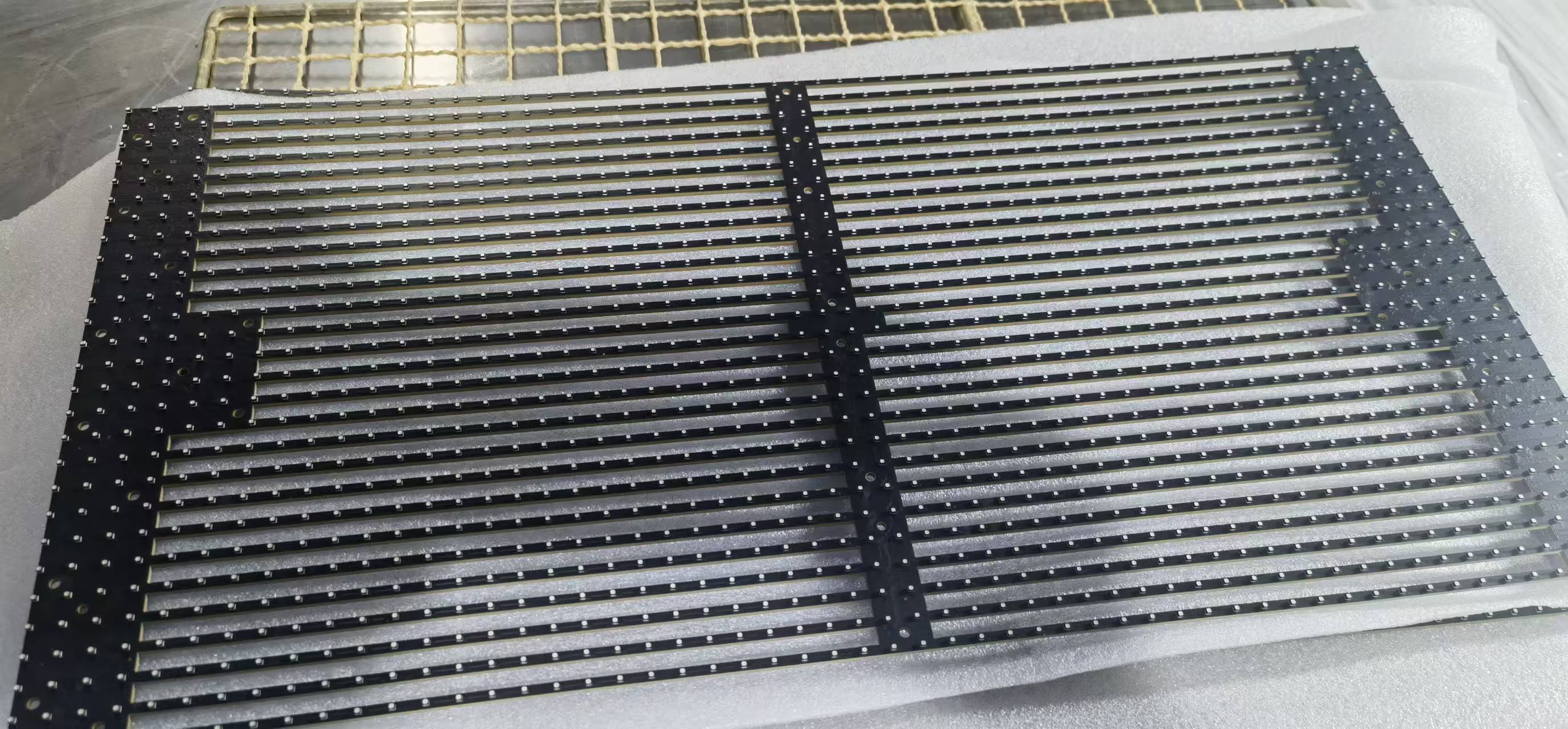
LED module before silicone encapsulation
Before: LED strips and frame exposed; coverage area and gate position follow the component layout.
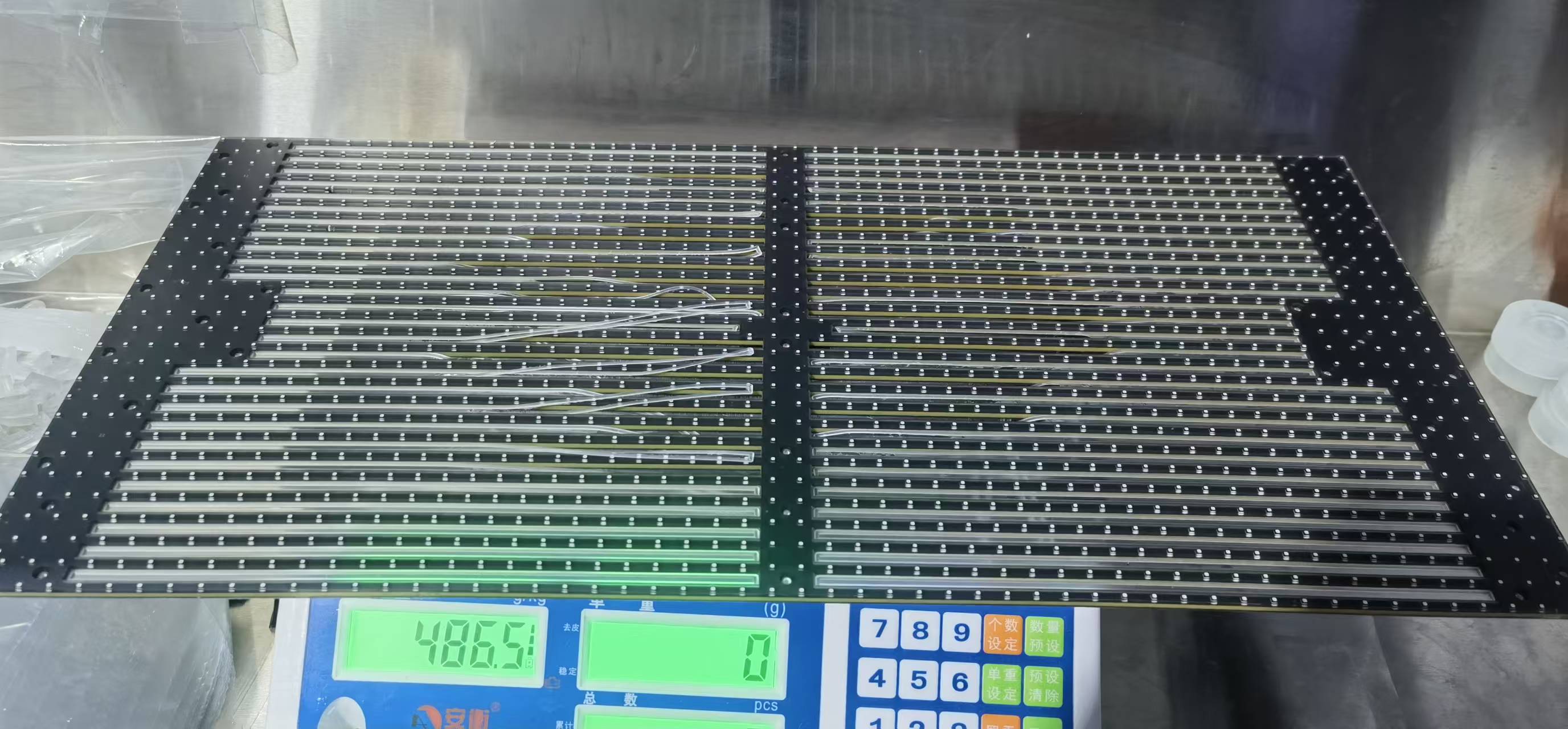
LED module after silicone encapsulation
After: the board surface is covered in one silicone layer; shot weight can be checked by weighing the finished part.

Related directions

Other composite molding cases

Glass protection follows the same idea: wrapping tempered glass in a silicone edge has to absorb a glass thickness tolerance of about 0.03 mm, keep the glass centred on all four sides, and still resist impact and disassembly. Metal inserts and PCBA assemblies are the two parallel main lines, judged by the same logic.

Material and hardness options are set out in material selection, surface effects in surface finishing, tooling and molding routes in molding and tooling, and interface bonding and verification in bonding to other materials.

Close-up of a silicone overmolded metal insert part
Insert overmolding

Metal insert overmolding

The metal carries strength and the connection; the silicone covers and seals. Both are joined in one molding cycle, and the assessment centres on insert location and coverage area.

See the capability
Silicone composite part overmolded onto a PCBA
PCB assembly

PCBA overmolding

Composite molding built around a circuit board for water, dust or impact protection, with gate positions laid out around the components.

See the capability

Common questions

Chip overmolding and LED encapsulation

Does overmolding change the read range of an RFID chip?

Coverage thickness, the dielectric properties of the compound, and how the chip and antenna sit relative to each other all affect reading. At proposal stage we confirm the chip and antenna package first, then fix coverage thickness and position, and verify by actually reading the part during sampling.

Can the chip be damaged by heat during molding?

This is the main risk in chip overmolding. We confirm what the chip and antenna can take, then set molding temperature and injection and packing parameters so the silicone cures without damaging the internal structure. With runner design controlling the fill force, the encapsulated chip still works and can be used repeatedly.

Can the chip be pushed off position inside the mould?

During clamping and filling the chip sees forces from six directions. Our positioning method holds displacement to within 0.5 mm per side, and runner and gate positions are arranged so the fill does not squeeze the chip, which keeps it where the design puts it inside the coverage layer.

What temperature range do the wristbands and laundry tags take?

On the sample products shown here, the wristband is marked -20 to 180 degrees C and the laundry tag -50 to 250 degrees C. For a project the operating temperature is confirmed from the actual use case before a compound is chosen.

What changes when silicone replaces resin on an LED module?

Four things are checked: how the encapsulation layer holds up under UV and thermal cycling outdoors, how brightness and viewing angle change after coverage, whether the water and dust path across the board is continuous, and how the module can be reworked or repaired later.

Can wristbands be customised in colour and print?

Yes. Printing, spray coating, laser marking and colour filling are the usual options for this product type. Colour and artwork are confirmed from the drawing supplied by the customer, and physical samples are checked at sampling.

Can these cases be ordered as they are?

The page explains the directions we take on and how the decisions are made. A real project needs the chip type or a drawing, the operating environment and the assembly requirement; structure and coverage are assessed first, then tooling and sampling are arranged.

A chip or an LED module to encapsulate?

Send the chip type, the operating environment and the appearance requirement. Structure and coverage are confirmed first; tooling and sampling come after that.

Send an inquiry