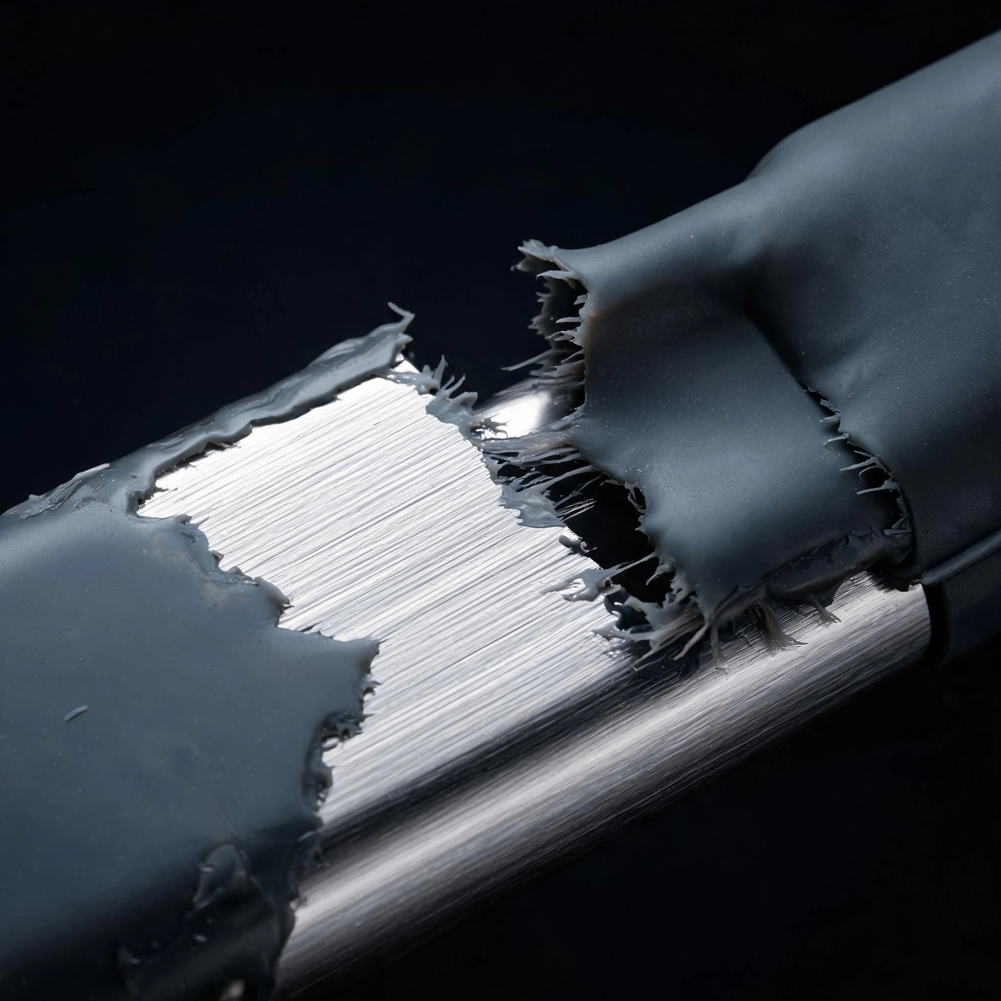
When an overmoulded part delaminates, the first reaction is almost always to adjust the machine: raise injection pressure, lengthen cure time, lift mould temperature. Those three moves almost never fix it.
The reason is simple: bond strength is set by interface chemistry; injection pressure only changes how the melt reaches the interface. For a material pair that has already failed on chemistry — untreated PP against a standard LSR — going from 60 MPa to 120 MPa will not change peel strength in any meaningful way. It will only produce worse flash.
This note works from the interface outward: why silicone refuses to stick, what each of the three bonding routes can and cannot deliver, a substrate matrix you can look things up in, eight failure modes with symptoms and root causes, and what to actually demand at acceptance. It is drawn from arguments that repeat in project reviews, plus published supplier technical data.
1. Set the order of diagnosis first
Seeing delamination and reaching for pressure, cure time and mould temperature is the industry reflex. A more accurate approach looks for root causes at three levels: material selection, tooling, and process capability. Of the defects that show up most often, only a few are genuine parameter problems; the rest point at design or material.
So the working order is: measure surface energy → check contamination → check activation age → check primer consistency → check cure state → check whether the material pair was changed → and only then touch the process window. The value of that order is that the first five steps can all be done on the line. Adjusting parameters is the one action that looks like solving the problem while covering it up.
2. Why silicone does not stick: the surface energy table
To wet a surface, the liquid must have a lower surface energy than the solid. LSR sits at 20–24 mN/m — lower than almost every engineering plastic. That is why it does not stick to the mould, does not pick up dust, releases cleanly, and also why it does not stick to your substrate.
| Material | Surface energy | What it means |
|---|---|---|
| LSR (addition-cure liquid silicone) | 20–24 mN/m | Very low. No mould sticking, no dust pickup, good biocompatibility — and no bonding |
| PP / PE | 29–31 mN/m | Slightly higher than silicone, still in the "will not bond" band |
| PEEK / PPSU | Low, falling as crystallinity rises | A built-in weakness of high-performance plastics |
| PC (untreated) | 30–45 mN/m | Polar enough to wet, but the bond is van der Waals only |
| PC (after plasma) | 55–60 mN/m | The threshold for reliable wetting |
| Aluminium (clean, intact oxide) | High | Surface energy is not the problem — the weak boundary layer is |
| Stainless steel (untreated) | High | Same: the passive layer is inert |
Untreated PC can just about be wet by silicone, but the result is van der Waals bonding — measured peel strength typically below 2 N/mm, while medical and automotive programmes usually write 3.5 N/mm into the specification. That 1.5 N/mm gap is the entire reason overmoulding is a process rather than a materials choice.
3. Three routes that turn "will not stick" into "sticks"
| Route | What it actually does | Ceiling | Cost |
|---|---|---|---|
| Chemical bonding (primer or self-bonding LSR) | A silane couples to substrate functional groups at one end and joins the platinum-catalysed addition at the other — a molecular bridge | High (3–8 N/mm; better systems higher) | More steps, VOCs, primer uniformity hard to control |
| Physical activation (plasma, corona, laser) | Introduces hydroxyl and carboxyl groups, pushing surface energy to 55–60 mN/m | Medium-high (with chemical bonding, cohesive failure) | Time-limited: overmould soon after treatment |
| Mechanical anchoring (undercuts, serrations, laser texturing) | Silicone fills microfeatures and carries shear geometrically | Medium (adds 30–50% to the combined result) | Features must be cut into the substrate first |
The key point: you combine these, you do not pick one. Mechanical anchoring cannot replace chemical bonding on its own — it can add 30–50%, but 30–50% of zero is still zero. Equally, chemical bonding alone is not enough: silicone expands at roughly 250–300 ppm/°C against about 47 ppm/°C for PEEK, a factor of five or more, so thermal cycling keeps loading the interface in shear until it starts cracking in from the edge. That is where "passed the sample, failed the reliability test" comes from.
4. The fracture face matters more than the number
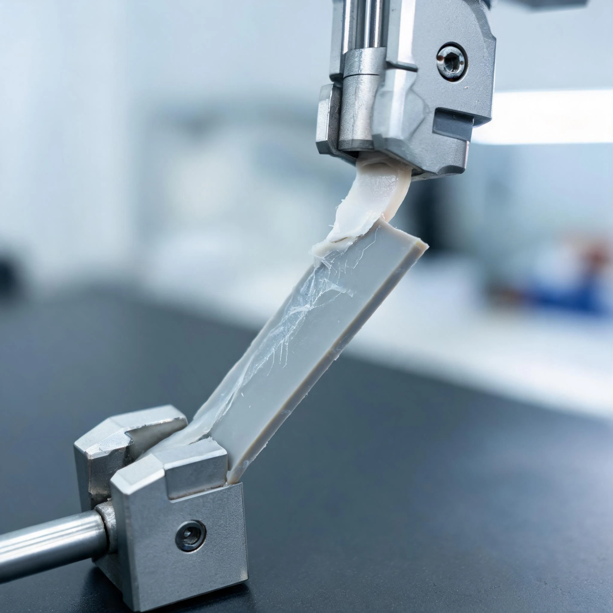
A peel report that says "5.2 N/mm, pass" does not tell you enough. What matters is what the fracture surface looks like.
| Failure mode | What you see | What it means | Verdict |
|---|---|---|---|
| Adhesive failure | Silicone peels off clean; substrate is glossy | Bonding has effectively failed; only edges or local spots hold it | Reject, however high the number |
| Cohesive failure | Silicone itself tears; a layer stays on the substrate | Interface strength exceeds the bulk strength — the material limit | Genuinely acceptable |
| Mixed failure | Partly residual, partly clean | Interface is near the threshold | Judge against aged retest |
Some supplier data sheets state both the number and the failure mode, for example ≥10 N/mm at 90° on PC for a self-bonding grade, annotated "cohesive failure in the silicone". That annotation matters far more than the number: it says the system has reached the material limit, so further process optimisation will not help; the next thing to look at is the tear strength of the silicone itself.
One line for purchasing: ask for photographs of the fracture face, not just a number. Numbers alone are how "good-looking fake bonds" get through.
5. The substrate matrix: plastics, metals, and two things not to promise
5.1 Plastic substrates
| Substrate | Untreated bondability | Recommended route | Typical peel | Main risk |
|---|---|---|---|---|
| PC | Poor (van der Waals only) | Self-bonding LSR / plasma + primer / mechanical interlock | Self-bonding 1.8–5; premium grades up to 10 (cohesive); primer 5–8 | Mould release residue forms a separating layer; flame-retardant and glass-filled grades bond worse; platinum inhibition |
| PC/ABS | Medium | Self-bonding LSR | 2–4 | ABS phase has limited thermal stability, capping mould temperature |
| ABS | Medium | Self-bonding LSR | 1.5–3 | Butadiene phase degrades at temperature |
| PBT | Medium | Self-bonding LSR / primer | 2–4 | High crystallinity, large cooling shrinkage; glass-filled grades lose surface energy |
| PA6 / PA66 | Medium-high | Self-bonding LSR | ≥2.0 (some systems 3+) | Above 30% glass fibre the surface chemistry is too weak — mechanical interlock only; hygroscopic, dry to below 0.1% moisture |
| PPSU | Poor | Plasma or laser activation + dedicated primer + mechanical interlock | 3–5 (to be validated) | Very low surface energy; large CTE mismatch |
| PEEK | Very poor | Laser texturing + plasma + annealing | Medical grips ≥2.0; up to 5.2 when optimised | Residual stress causes delayed cracking; annealing mandatory |
| PP / PE | Not bondable | Mechanical interlock only / hot melt / change substrate | — | Do not promise it in a quotation |
| TPU / TPE | Medium | Self-bonding LSR or a compatible family | 2–4 | Plasticiser migration attacks the interface; small molecules poison the catalyst |
| POM | Poor | Practically not bondable without special primers | — | High surface crystallinity and easy release; it repels by nature |
On PP/PE, plainly: "PP primers" and flame treatment do exist, but they do not reach medical or automotive reliability, and batch consistency is poor. Promising that "we can overmould PP too" in a quotation plants a problem that goes off about six months later.
On glass-filled PA there is a specific threshold: above 30% glass, fibre concentrates at the surface, the amide groups available for bonding drop, and roughness creates a mass of micro air traps. Such parts can only be anchored mechanically with undercuts and texture; the chemical route is effectively off the table.
5.2 Metal substrates: the problem is the weak boundary layer, not surface energy
Metals have high surface energy, so in theory they should bond well, yet they often do not. The oxide, passive layer or oil film is itself a weak boundary layer: under load the joint fails inside the oxide rather than between silicone and metal.
| Substrate | Surface preparation | Coupling agent | Typical peel | Control point |
|---|---|---|---|---|
| Stainless steel | Blast Ra 1.6–3.2 μm + pickling and passivation | KH-550 (amino silane) | >7 N/mm with a dedicated primer system | Finish to a uniform grey-white; the passive layer must be broken |
| Aluminium | Blast + anodise 5–8 μm | KH-560 (epoxy silane), 120°C for 10 min after spray | >6 N/mm; self-bonding LSR ≥2.5 direct | Too thin an oxide is a weak boundary layer; too thick and it cracks |
| Copper / brass | Blast + anti-oxidation | KH-560 or a dedicated primer | 5–7 N/mm | Oxidises fast — overmould promptly; a few hours in air can kill it |
| Magnesium alloy | Conversion coating / anodise + sealing | Dedicated system | Validate per project | The silicone layer must fully seal; no pinholes |
| Nickel-plated magnets | Plating integrity check | Silane primer | Validate per project | Pinholes start corrosion; magnets dislike heat, so agree mould temperature |
From the line: nine out of ten metal overmoulding delaminations are not a glue problem, they are surface preparation that was not done properly. Purchasing can ask for three things — the preparation route in writing (blast roughness, primer type, time between preparation and overmoulding), peel test records per batch, and moulding parameter records.
Primer film is normally kept at 1–3 μm and dried at 80°C. Thicker is not safer: an over-thick primer becomes its own weak layer, because its cohesive strength is lower than the load it has to carry, so the joint fails inside the primer.
6. Three number traps
6.1 Units: N/cm and N/mm differ by a factor of ten
Three expressions circulate at once: N/mm (the international norm), N/cm (common in China; 1 N/mm = 10 N/cm), and MPa (lap-shear strength, a different quantity that does not convert). A real example: a supplier writes "peel strength ≥8 N/cm", which is 0.8 N/mm. Medical and automotive programmes often ask for 3.5 N/mm, i.e. 35 N/cm. The "8" looks larger than "3.5"; in fact it is 23% of the requirement. Write the unit and the test standard into the specification.
6.2 Numbers are not comparable across sources
The same phrase "peel strength on PC" turns up as 1.8, 3.5, 5 and 10 N/mm — a five-fold spread. Nobody is lying; the test angle (90° or 180°), specimen geometry (standard coupon or real part), peel rate, substrate grade (standard PC, flame-retardant PC, glass-filled PC) and silicone grade all differ. Only compare figures taken under the same standard, the same substrate grade and the same silicone grade. Cross-source numbers are order-of-magnitude references, never acceptance criteria.
6.3 Initial value is not durability
Peel strength straight off the line and peel strength after 50 autoclave cycles, 500 hours of 85/85 damp heat or 100 thermal shocks from -40 to 125°C can differ by more than 40%. The real life of an overmoulded joint is the residual strength after ageing, which is why professional RFQs state "retest after ageing" explicitly.
7. Choosing between the routes
The decision logic can be short:
- PP / PE / POM: drop chemical bonding, use mechanical interlock only, or change substrate;
- PEEK / PPSU: laser or plasma activation + mechanical interlock + annealing, with a primer only as support;
- Mainstream engineering plastics (PC / PBT / PA / ABS): high volume and automation point to self-bonding LSR; small batches with standard LSR in stock point to primer;
- Metals (stainless, aluminium, copper): blasting + matched coupling agent + preheat;
- PCBA: vacuum + flux removal + low pressure, slow fill + selective primer.
7.1 Self-bonding LSR is not universal
Self-bonding grades add a bifunctional adhesion promoter, forming covalent bonds and mechanical anchoring during cure. The advantages are real: no primer, no mould sticking, fast cure, suited to automated two-shot moulding. But there are three hard limits.
- A grade does not bond every substrate. "Self-bonding LSR" is a family; a grade that works on PC may do nothing on PPSU. Validate the material pair — do not order from a data sheet alone.
- Change the substrate and the bond can disappear. A new PC supplier, a different flame-retardant package, a different glass loading can all break a validated interface. Once validated, freeze the pair — including the exact substrate grade and supplier — and write that into the quality agreement.
- It is more contamination-sensitive than a primer. The promoter has to orient on a clean surface; a trace of mould release is enough to fail a whole batch, and it shows up as "tacky in places", which is easily misread as a process problem.
7.2 Primer: strong, but consistency is the soft spot
Primers reach higher strength; 5–8 N/mm is a normal band for a mature process, and dedicated metal systems go higher. The fatal weakness is the number of human steps: clean, activate, spray, dry, control the open time, load. Every step can add variation, and the result is "80% of the batch is fine, 20% delaminates" — the hardest failure to trace, and the easiest to paper over with "apply a bit more". The core of a primer route is not choosing the right primer; it is controlling application consistency: 1–3 μm film, uniform coverage, drying temperature and time, and the window between primer and overmoulding.
7.3 Plasma and laser: the shelf life trap
Plasma lifts surface energy to 55–60 mN/m and drops contact angle from 80° to below 30° — a large, visible effect. One number belongs in the work instruction: activation starts decaying within 30 minutes; parts not overmoulded within that window must be re-activated.
The physics is simple: the polar groups re-orient, bind airborne contamination, or migrate inward, and surface energy drifts back towards the untreated value. "Activation window overrun" is not a parameter error, it is failed time management — the treatment station sits in another bay with a two-hour transfer, treatment runs into the lunch break, or a whole day's parts are treated at once for efficiency. The sample was treated in the morning and moulded immediately, so of course it held; production treats in batches and moulds the next day, so of course it fails.
8. The eight failure modes
Start with the quick table, then read the entry you need.
| # | Failure mode | Most likely root cause | First action | Sample passes, volume fails |
|---|---|---|---|---|
| 1 | Interfacial delamination | Low surface energy / contamination / expired activation | Measure surface energy; check time from treatment to moulding | Common |
| 2 | Cohesive tear | Tear strength too low / stress concentration | Switch to a higher-tear grade; add radii | No |
| 3 | Voids and air traps | Insufficient venting / air entrapment / moisture | Deepen vents; use multi-stage injection | Moderate |
| 4 | Flash | Parting line precision / vents too deep | Check tool gap; use a knife-edge shut-off | No |
| 5 | Short shot and air burn | Unbalanced fill / no vent at the end | Flow analysis; add venting | No |
| 6 | Platinum poisoning | Sulphur / tin / amine / flux contamination | Dedicated tools; wash boards; nitrile gloves | Most common |
| 7 | Substrate distortion, die crack | Mould temperature above Tg / pressure / unbalanced flow | Lower mould temperature; symmetric tool; low pressure, slow fill | Common |
| 8 | Dimensional drift | Poor shrinkage compensation / uneven mould temperature | Zone-controlled temperature; validate per batch | Moderate |
Failure 1: interfacial delamination
Symptoms. Silicone separates from the substrate with a clean fracture and a glossy substrate; it may happen at demoulding or after two to six months in the field. Mechanism. The interface carries no real chemical bonds or mechanical anchoring, only van der Waals forces; a crack starts and runs along it.
Root causes, most frequent first. Insufficient surface energy (untreated or expired activation); contamination (release agent, oil, dust, fingerprints, packaging film residue); missing, uneven or under-dried primer; additive migration in the substrate (release agents and flame retardants in PC keep migrating to the surface and form a separating layer); under-cure; expired activation window; accumulated CTE mismatch.
Prevention. Standardise preparation: IPA ultrasonic degrease for 5 min, 80°C hot-air dry for 30 min, plasma for 30–60 s, then mould within 30 minutes. Set a surface-energy gate: measure contact angle or dyne value on the line and release only at 56 mN/m or above. Keep substrate moisture below 0.1%. Keep a mechanical fallback: undercuts at least 0.5 mm deep (0.6 mm and 35° draft for PEEK) and a textured surface at Ra 1.6–3.2 μm.
Failure 2: cohesive tear — the one most often misread as delamination
Symptoms. The silicone itself tears and leaves a layer on the substrate. It looks like delamination but the conclusion is the opposite. It gets its own entry because treating it as delamination makes things worse: pressure goes up, primer goes on, grades get swapped, while the real issue is insufficient tear strength in the compound or a structure that concentrates stress.
Root causes. Low tear strength (especially very soft 20–30 Shore A LSR); a wall under 0.5 mm that cannot spread load; sharp internal corners or abrupt section changes; excessive ejection force or badly placed ejector pins.
Prevention. Move to a higher tear strength grade (usually the only effective action); keep the silicone wall at 1.5–2 mm, never below 0.5 mm; radius all internal corners; place ejectors on rigid areas. The method is simply to peel and photograph: silicone left on the substrate means cohesive failure.
Failure 3: voids and air traps
Symptoms. Voids inside the part or at the interface, visible or only under industrial CT or ultrasound. For seals and water-resistant parts this is the most direct leak path. Mechanism. Gas is not evacuated before the silicone arrives, or the melt envelops it and it cannot rise.
Root causes. Vents too shallow or badly placed; injection too fast, creating turbulent air entrapment; compound not de-gassed; moisture in the substrate (PA and PBT not dried, steam forming at temperature); geometry that traps air (closed cavities, deep pockets, gaps between components and board); dense PCBA without vacuum assist.
Prevention. Vents at 0.02–0.03 mm (over 0.03 mm and the same vent flashes — the two defects are a matched pair); multi-stage injection, starting at 10–20 mm/s laminar flow, 30–50 mm/s for the body, dropping to 5–10 mm/s at the end into pack; compound de-gassed below 3 mbar for 30–45 min; substrate preheat at 80–100°C to drive off moisture; PCBA under 10 mbar vacuum. Detection. Visual, sectioning, industrial CT (0.01 mm voids), and air-decay or hydrostatic leak testing.
Failure 4: flash
Symptoms. Thin silicone at the parting line or along the overmoulding border, needing manual trimming; in bad cases it interferes with assembly or the sealing face. Mechanism. Uncured LSR is close to water in viscosity and will enter any micron-level gap. This is one of the essential differences from solid silicone: flash control in LSR depends entirely on tool precision, not on the material.
Root causes. Parting line fit worse than 0.01 mm; vents deeper than 0.03 mm; excessive injection pressure or insufficient clamp; tool wear; insert misalignment opening a local gap.
Prevention. Parting line fit within 0.01 mm, flatness within 0.005 mm; a knife-edge shut-off at the overmoulding boundary with 5–20 μm clearance; staged packing instead of ever more clamp force; tool life management with periodic gap checks. Acceptance. Flash no thicker than 0.05 mm; sealing faces should have no flash at all — trimming damages the sealing face, so "we trim it" is not a fix.
Failure 5: short shot and air burn
Symptoms. Unfilled ends, local blackening from burnt gas, or trapped air inside — most common on thin walls and complex geometry. Mechanism. Two different problems: a short shot is the melt stalling before the end of flow because it cooled or lost pressure; air burn is trapped gas compressed adiabatically until the temperature spikes and the silicone degrades.
Root causes. Unbalanced fill in multi-cavity tools (over 5% flow variation between cavities); poor gate location; no vent at the end of fill; an injection profile that does not match the geometry. Prevention. Run flow analysis at design stage; hold cavity-to-cavity variation within 5%; add venting at the end of fill, deep pockets and weld lines; use a staged profile and slow down at the end.
Failure 6: platinum poisoning — the most hidden one
Symptoms, two levels. Mild: the part has cured inside but the contact surface, especially the mould face, stays oily and tacky. Severe: the mixed compound stays liquid after heating or standing, with no viscosity change at all.
Mechanism. Addition-cure LSR relies on a platinum complex to catalyse the hydrosilylation of Si-H with vinyl. Platinum is delicate: lone pairs on contaminant molecules form coordination bonds more stable than vinyl does, occupy the active centre, and the chain reaction stops.
The poison list. Sulphur compounds (sulphur-bearing release agents, vulcanised rubber, latex gloves, sulphur soap — the worst, effective at traces); organotin (residue from condensation-cure RTV, shared tools); nitrogen compounds (amine epoxy curatives, some cleaners, excess amino silane); phosphorus compounds (flame retardants, stabilisers); heavy metals; flux residue (unwashed PCBA — no cure locally plus bond failure); polyols and solvents; sweat and skin care products.
Why it hides. It does not present as "will not stick" but as "tacky in places" or "this batch looks odd", so the line blames expired compound or unstable mould temperature and keeps adjusting without finding it. Worse: if any machine in the same shop has run condensation-cure silicone, residual tin is enough to scrap an entire batch of addition-cure LSR.
Prevention is management, not parameters. Dedicated tools — containers, spatulas and dispensing equipment must never be shared with condensation-cure RTV; this one rule outweighs all the others. Nitrile gloves only; no bare-hand contact through latex. No sulphur or tin release agents in the tool; use platinum-safe release or silicone oil. Wash PCBA even with no-clean flux. Run a small cure test on any unknown substrate or new material lot. Keep the A/B ratio accurate with calibrated metering pumps and scheduled static mixer changes — a ratio error produces marbled compound that is hard in places and tacky in others.
One extension. The Si-H to vinyl molar ratio is usually held at 1.2–2.0. Low means incomplete cure and tackiness; high leaves excess Si-H, which can generate hydrogen bubbles in humid conditions. So "a bit more crosslinker for safety" is also wrong.
Failure 7: substrate distortion and die cracking
Symptoms. Warped substrate, displaced inserts, cracked solder joints — the most serious PCBA overmoulding failure because it cannot be repaired. Mechanism runs along three independent paths. Heat: mould temperature above the substrate Tg softens it and injection pressure deforms it. Force: injection pressure pushes inserts out of position or bows the board. Flow: unequal thickness above and below the board makes the melt front arrive unevenly, and the pressure difference bows the board. A bowed board bends the lead frame, stresses the die, and cracks appear in solder joints or in the silicon — cracks that pass final test and fail at the customer.
Root causes. Mould temperature above substrate Tg; asymmetric top and bottom tool halves; insert location worse than ±0.01 mm; a gate aimed at a sensitive component or a metal edge; excessive injection pressure. Prevention. Keep mould temperature below substrate Tg and measure the cavity surface, not the controller setpoint; keep PCBA tools symmetric and verify with flow analysis; use precision location and preheat inserts close to mould temperature; keep gates away from components and metal edges; pot large components first; inject at low pressure and slow fill. Detection. Full functional retest after overmoulding, X-ray on solder joints, and cross-sectioning where needed.
Failure 8: dimensional drift and warpage
LSR shrinks about 2–3% linearly from a 150°C mould to room temperature, and batches can differ by another 0.3%. Root causes. No shrinkage compensation in the tool; uneven mould temperature; insufficient packing; demoulding too early; batch-to-batch shrinkage not tracked. Prevention. Compensate at design stage and re-verify per batch rather than once; zone-controlled temperature within ±1°C; packing pressure and time matched to wall thickness; longer in-mould cooling or fixturing after demoulding; sample every material lot. Reference. Normal LSR tolerance is ±0.08–0.13 mm; critical features reach ±0.02–0.03 mm with a micro reciprocating screw and closed-loop metering.
One shared feature deserves its own sentence: modes 1, 6 and 7 all depend on time or environment, not on a setpoint. The sample stage is ideal — treated the same day, moulded the same day, clean room. Production is real — next day, dust, shift handover. A passing sample never proves volume feasibility; it only proves the material pair can bond in theory.
9. Two case reviews
Both cases come from published supplier technical data and are used to show the logic of failure; validate the parameters in your own process.
Case A: PEEK endoscope handle, delamination after 35 sterilisation cycles
A PEEK handle overmoulded with 1.2 mm of soft compound (same mechanics as LSR). Initial validation had passed, but after 35 cycles at 134°C the part showed 0.45 mm of delamination, and industrial CT found 0.3 mm voids inside — enough to block sterilisation validation.
Two root causes together. First, gate design: a 0.5 mm pin gate produced shear rates above 75,000 s⁻¹, jetting and air entrapment, and persistent internal voids. Second, no mechanical anchoring: PEEK surface energy is very low and the joint relied on chemistry alone, so thermal cycling kept accumulating shear at the interface.
The fix: a 0.8 mm fan gate replaced the 0.5 mm pin gate, cutting shear rate by about 45%; 0.02 mm vents around the perimeter removed the entrapment; the PEEK substrate received 0.6 mm undercuts at 35° draft so the interlock carried shear; and mould temperature became dynamic, holding the PEEK surface at 145 ± 1.5°C for micron-scale surface remelting — which removed the plasma step altogether.
The result: 500 first-off parts with zero voids on CT; 5.2 N/mm bond strength; 150 cycles at 134°C plus 50 kGy gamma with zero defects; and 0.35 USD lower cost per part after the plasma step was dropped.
Three lessons. The root cause of "delamination after sterilisation" can sit in the gate, not in the bond, because voids are moisture paths. Mechanical anchoring can replace surface treatment under specific conditions. And the timing of DFM decides the cost: the same issue found before the tool is cut costs nothing; found afterwards it costs an order of magnitude more.
Case B: insulin pump reservoir, 8% leak rate
A medical-grade silicone seal overmoulded onto PEEK failed leak testing at 8% during line validation. Two causes: gate location produced uneven flow and a weak zone at the interface; and plasma treatment was inconsistent — the station existed but had no process monitoring, so batch drift went unnoticed.
The fix: relocate the gate; install an automated plasma station with real-time monitoring; optimise the mould temperature curve. The result: leak failures fell from 8% to below 0.5%, 200 consecutive autoclave cycles with zero delamination against a 50-cycle requirement, and a clean 510(k).
The lesson in one line: having a plasma unit and having effective plasma treatment are two different things. Surface treatment without process monitoring is no surface treatment, because you cannot know when it stopped working.
10. Acceptance: proving the bond is real
| Test | Standard | Purpose | Acceptance reference |
|---|---|---|---|
| 90° / 180° peel | ASTM D1876 / D429 | Interface strength | ≥3.5 N/mm with cohesive failure |
| Lap shear | ASTM D1002 | Shear capacity of a flat bond | Defined by application |
| Thermal cycling | -40°C to 85 / 125 / 150°C | Interface fatigue from CTE mismatch | No cracking; strength retention >70% |
| Damp heat | 85°C / 85% RH for 500–1000 h | Hydrolytic ageing | No delamination |
| Boiling water | 100°C for 30 min | Fast screen for weak interfaces | No lifting, no separation |
| Autoclave | 134°C for 50–200 cycles | Medical specific | Zero delamination; retention >70% |
| Chemical immersion | Alcohol, iodine, coolant, etc. | Compatibility with the real medium | No swelling, no delamination |
| Industrial CT | — | Internal voids | No defect at 0.01 mm or above |
Three requirements to write into the RFQ:
- Ask for fracture photographs, not only numbers. A number can look excellent while the failure is adhesive.
- Ask for aged data, not only the initial value. Initial strength is the entry ticket; residual strength after ageing is the life.
- State the unit and the standard. N/mm or N/cm, 90° or 180°, standard coupon or real part — this single line removes most later arguments.
One counter-intuitive closing note: do not use "raise the injection pressure" as a cure for poor bonding. Pressure improves fill, not chemistry. When the bond is short, the order is: measure surface energy, check contamination, check activation age, check primer consistency, check cure, confirm the material pair is frozen — and only then open the process window.
11. Ten questions for purchasing and engineering
These can go straight into a supplier assessment. A supplier who answers them one by one is at a different level from one who cannot.
- Which standard, angle and unit do you use for peel testing? Can you provide fracture photographs?
- What is the window between plasma or primer and overmoulding, and how is it monitored?
- How do you verify incoming substrate surface energy? Is it checked on the line?
- Is the self-bonding LSR material pair — substrate grade plus silicone grade — frozen? How are material changes managed?
- What is the parting line fit on the tool, and what is the knife-edge clearance?
- Are addition-cure tools fully segregated from condensation-cure? What release system is used?
- What vacuum level do you reach on PCBA overmoulding, and how is flux residue handled?
- In failure analysis, how do you distinguish adhesive from cohesive failure?
- Can you provide retest data after ageing — thermal cycling, sterilisation, damp heat?
- In your last project, what were the three most common defects in volume, and how did you fix them?
The tenth question is the most telling: suppliers who answer it in detail are usually the ones who actually solve problems on the line.
What this means in practice
Overmoulding failure looks like a process problem but is usually a selection and interface problem. Treat it as interface engineering: confirm the material pair can bond, decide which route will produce the bond, then prove it with fracture faces and aged data. Machine adjustment belongs last, not first.
Further reading: the substrate and primer comparison is in material and primer matrix; the bonding overview is in bonding to other materials; the validation scope is in R&D and testing; moulding conventions are in moulding and tooling. If you have a specific substrate and duty, send the drawing and we will start with a feasibility and risk view.