Material selection
Compounds chosen by structure, molding route and operating environment: rebound, tear strength, high and low temperature resistance, flame retardancy, anti-static, food-contact and medical grades. Shore A 0 to 90 is selectable.
Overmolding onto metal inserts, plastic parts and PCBA assemblies. We match material and molding method to the part's real operating conditions, and line up tooling, fixtures and machine options with volume and cost targets.
Capability system
This page covers structural judgement, project flow and production resources. Materials, surface finishing, tooling, interfaces and verification each have their own topic, and the decision they drive is summarised below.
Compounds chosen by structure, molding route and operating environment: rebound, tear strength, high and low temperature resistance, flame retardancy, anti-static, food-contact and medical grades. Shore A 0 to 90 is selectable.
In-mold texture, spray coating and plasma activation, screen and pad printing, in-mold transfer, laser marking and flocking, combined as the appearance and durability targets require.
Nine molding routes — compression, LSR injection, potting, blow molding, screen printing, spray coating, dispensing, extrusion and calendering — with solid, liquid, potting and cast tool systems.
Ultrasonic cleaning, plasma activation, primer matched to the substrate and temperature-controlled press curing, aimed at delamination and cracking at the interface.
Six testing groups: compound and formula analysis, mechanical and bond strength, weathering, electrical insulation, wear life and precision dimension.
Beyond standard presses, we modify or build dedicated machines and pair them with tooling and fixtures to lift cycle rate and consistency for structure-frozen, high-volume parts.
Parts with a finished product form to reference — silicone over RFID chips and liquid encapsulation of LED displays — are collected under applications.
Molding methods
Compression, LSR injection, potting and blow molding cover the common molded forms; screen printing and spray coating build surface function; dispensing, extrusion and calendering cover local functional layers, constant-profile sections and sheet or roll stock.
The mainstream route for solid silicone: high temperature and pressure cure with strong stability and controllable volume cost, suited to standard silicone parts and insert overmolding.
Liquid silicone injected under pressure into a closed mold and cured fast. High speed and repeatability, suited to thin precise walls and to medical or food-contact products.
Liquid silicone poured to fill and fully enclose PCBA, modules and small precision parts, giving waterproofing, moisture protection, insulation and shock absorption.
Air pressure presses melted silicone against the mold wall to cure, producing hollow parts with even wall thickness, good toughness and no seams.
Silicone ink printed through a screen and oven cured to form thin structures: graphics, local thickening, anti-slip texture and insulating coatings.
Automated spraying builds an even, dense silicone functional layer for anti-slip, wear resistance, insulation, waterproofing and release surfaces.
A dispenser lays liquid silicone along a programmed path and cures it in place — no tooling needed, fast to sample. Suited to thin functional layers, local thickening for cushioning, anti-slip and sealing beads, and to small batches where the structure is not frozen yet.
Solid silicone is pushed continuously through a die and cured in line, giving constant-profile strips, tubes and cords of unlimited length: sealing strips, profiled strips, silicone tubing and foamed silicone strips.
Multi-roll calendering presses compound into sheet or roll stock of even thickness, cured afterwards and then die cut, punched or trimmed: silicone sheet, gasket substrate, insulating cushion pads and foamed silicone sheet.
The method, the products it suits and the items to confirm for each route are described on the tooling and molding page.
Silicone itself molds easily. The hard part is holding it firmly and sealing it onto another material. How the insert is fixed, how much coverage to leave, where the parting line runs, whether the gate position will displace or cut the structure — these must be settled before the tool is cut, otherwise the problem only shows up at sampling or in volume.
We assess structure and load first, then material and molding method, and only then tooling and process parameters. The assessment states which conditions hold, which items the customer must confirm, and what the sampling stage should verify.

Overmold structures
The same structure type raises different questions in different projects. These are the points we usually confirm first.
The metal part carries strength and connection, the silicone covers and seals; the two are joined in one molding cycle.
The rigid plastic carries structure and assembly faces while silicone provides sealing, cushioning and touch, as in keys, sleeves and clip components.
Composite molding around a circuit board for waterproofing, dust protection or shock absorption.
Sealing rings, gaskets and profiled structural parts, where dimensions and compression set decide how well the seal works.
Applications
The structural reasoning is the same, but chip products and display encapsulation differ sharply in coverage thickness, fill path and operating environment.
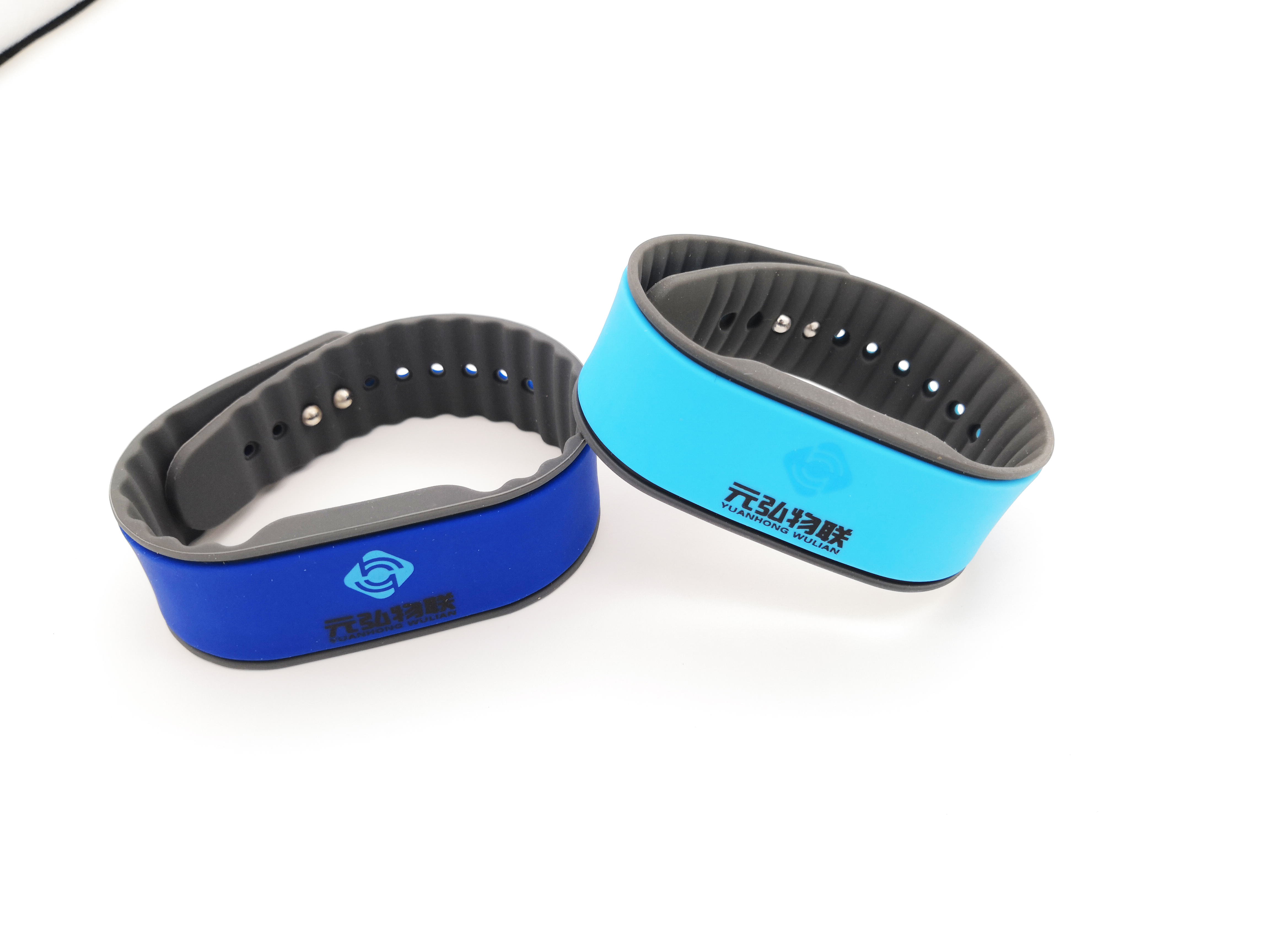
Chip and antenna are encapsulated in silicone for wristbands, NFC rings, pet tags and laundry or cold-chain labels. The assessment balances coverage thickness, chip position and read performance.
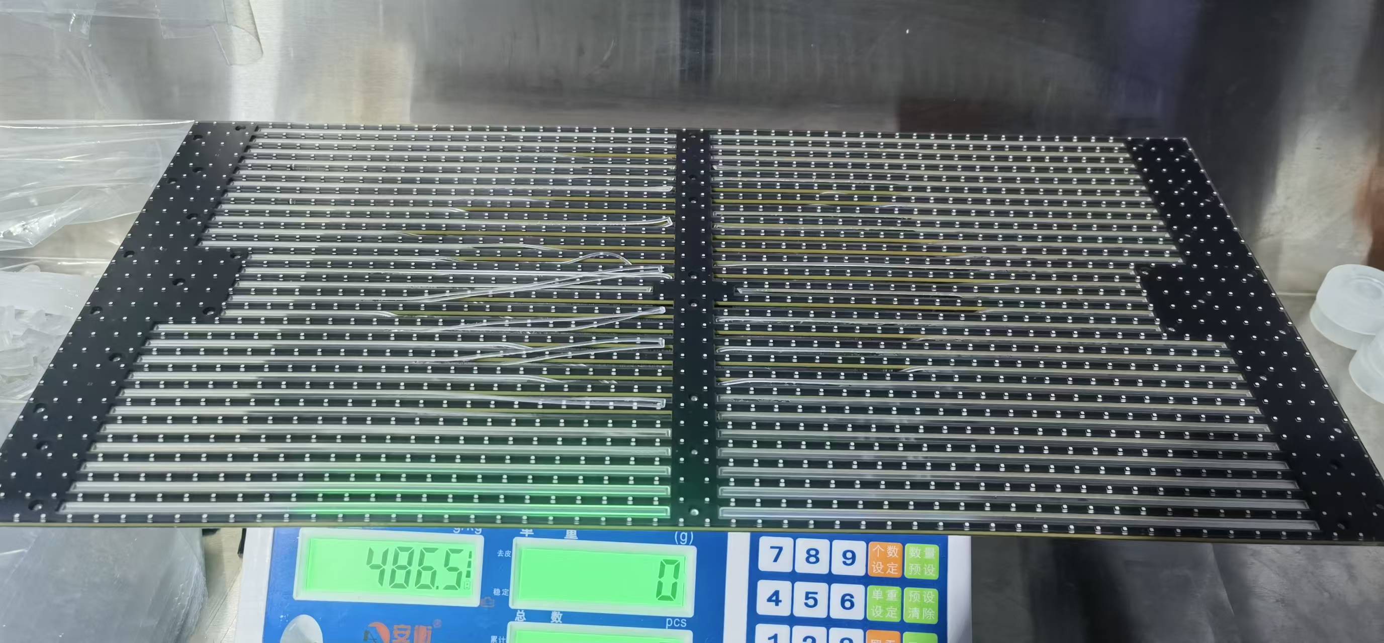
Precision liquid encapsulation covers the module surface as an elastic protective layer instead of resin potting, coping with outdoor UV and thermal cycling. The assessment focuses on flow path, coverage thickness, weathering and the water-sealing path.
Hardness, colour, surface feel and temperature resistance are confirmed around the structure. Hardness affects assembly feel and sealing compression; colour and surface feel define the appearance acceptance criteria and usually need a physical sample at the sampling stage.
Solid silicone compression molding suits smaller volumes, simpler structures or thicker silicone layers. Liquid silicone is stronger in flow, automation and batch consistency, and fits finer structures or larger volumes. The two are chosen per project rather than substituted.
Where the substrate is plastic, its temperature resistance and shrinkage must be considered as well, so that deformation during molding does not spoil the assembly.
Beyond hardness and colour, compounds offer selectable properties: high or slow rebound, high tear strength, ozone and ageing resistance, flame retardancy, anti-static, food-contact and medical grades. They are combined to the operating conditions rather than stacked item by item.
The tool structure decides where flash appears, how well the cavity vents and how accurately the insert is located. We confirm the parting line and gate position first, then decide whether slides, inserts or extra insert-fixturing are needed.
Insufficient venting causes short shots and burnt marks; excessive venting produces visible flash. On appearance-critical parts the planned flash position and the trimming method are agreed with the customer in advance, so that volume production does not stall on differing interpretations of the appearance standard.
The aim of sampling is not only to produce a sample but to freeze the process window — mold temperature, pressure, time and compound batch — as the basis for production.
Surface finishing also feeds back into tooling: in-mold texture must be cut into the tool, coating and printing need prior surface activation, and laser marking must account for light transmission on keys. Finishing should be agreed before the tool is cut rather than reworked afterwards.
Equipment and capacity
Standard presses solve standard needs. Once a product structure is frozen and volumes rise, cycle rate, labour content and unit cost usually hit the equipment limit. Beyond standard machines we modify or build dedicated machines and pair them with tooling and fixtures. The scope can be our own production line or equipment already installed at a customer or partner factory; this retrofit work is taken on as a stand-alone technical service.
Clamping, injection, ejection and part-removal motions are redesigned on a standard press, or a dedicated machine is built, so that the equipment matches the real molding cycle. For a frozen structure, output per machine and consistency are usually clearly better than on a general-purpose press.
Retrofit and tooling must be planned as one: cavity layout, gripper positions for automatic removal, and the locating and poka-yoke features for insert placement all have to be fixed before the tool is cut, or the modified machine still will not hit the cycle.
Starting from cycle time and the defect distribution, we judge whether machine, tool or process flow should change and give a retrofit plan. Work can be done in the customer's own workshop, with on-site commissioning and follow-up support.
| Item | Standard press | Modified / dedicated machine |
|---|---|---|
| Suitable products | Many product types, frequently changing structures, scattered volumes | Frozen structure, concentrated product range, high volume |
| Cycle and labour | Loading, removal and trimming rely on operators | Automatic loading and removal, little manual intervention, higher output per shift |
| Batch consistency | Affected by operator experience and machine condition | Motions and parameters fixed, smaller batch variation |
| Upfront investment | Low, flexible when models change | Retrofit and tooling cost must be amortised by volume |
| Order fit | Sampling, small batches and parallel models | High-volume orders and price-sensitive production |
Swim caps are a classic solid silicone part: simple, high volume, low unit price, and historically limited to a modest output per shift by machine type and manual removal. This was a retrofit on our customer's existing line — converting a standard press into a fully automatic swim-cap machine with a four-cavity tool lifted output to over 1,000 cycles per shift.
The same approach transfers to other products: stable structure, large order volume and price-sensitive categories see the most direct gain. As automation rises, output and consistency improve together and unit labour cost falls.
Conversely, where models change often, single-model volume is low or the structure is still moving, the flexibility of a standard press and general-purpose tooling matters more, and early investment in a dedicated machine is not justified.

Project flow
Every step has defined confirmation items, and the next step starts once they are agreed.
Collect drawings or samples and clarify the operating environment, assembly method and quantity range.
Judge overmolding feasibility and risk points, list open items and recommended options.
Confirm material, hardness, coverage range, appearance standard and tool structure direction.
Small-batch samples, trial assembly and critical dimension checks, to freeze the process window.
Molding to the confirmed window, with retrofit and automation fixtures for larger volumes, inspected and delivered to the agreed standard.
Defects
Locate the cause before changing tools or parameters; that is more effective than adjusting parameters at random.
| Symptom | Likely causes | Direction |
|---|---|---|
| Delamination, bond failure | Oil or release agent left on the insert surface; insufficient coverage | Confirm cleaning and surface treatment, adjust coverage and the bond-interface path |
| Flash, over-thick edges | Insufficient parting-line accuracy or oversized vents | Correct the parting line and vent structure, confirm clamping pressure and shot weight |
| Batch dimension drift | Uneven shrinkage, drifting mold temperature and molding parameters | Freeze the process window at sampling stage and define the measuring datum |
| Flow marks, bubbles | Poor gate position, insufficient venting, damp compound storage | Adjust gate and vent positions, control storage and preheating as the compound requires |
| Hardness or colour variation | Different compound batches, variation in mixing or ratio | Fix the compound batch and keep incoming inspection and mixing records |
| Chip displacement, changed read distance | Forces on the chip during clamping and filling; locating structure and runner cannot restrain it | Design locating features and runners around the chip position, hold displacement within 0.5 mm per side, and verify read performance at sampling |
FAQ
It depends on structure, volume and appearance. For complex structures and larger volumes, liquid silicone offers more in automation and consistency; for smaller volumes or simpler structures, solid silicone compression molding is more flexible. We recommend one after reviewing the project.
Cleaning and degreasing come first. Where needed we add surface treatment, or design a mechanical interlock to improve the bond. The method is confirmed against insert material, load requirements and operating environment.
Overmolded parts are normally molded. At the sample stage we confirm the structural option first and then decide the tool structure; whether a simple tool is enough for structural verification is judged per project.
Tolerance capability depends on part structure, hardness and the direction of the dimension. We confirm the achievable range for each critical dimension on the drawing and verify it at sampling.
Two extra constraints apply. First, components and solder joints are sensitive to pressure and temperature: on chip products we control three things at once — chip displacement during clamping and filling (our chip locating technique holds it within 0.5 mm per side), a molding temperature that does not damage the chip's internal structure so it stays reusable, and a runner and gate layout that does not crush the chip. Second, the covering layer must meet functional requirements such as RFID read performance or display light transmission and viewing angle. These projects normally need functional verification at sampling, not only dimensional and appearance checks.
Find the bottleneck first. If it sits in cure time and cavity count, the tool usually changes first — more cavities, better layout and runners. If time is consumed by loading, removal and trimming, machine retrofit with automatic handling and fixtures pays back more directly. Most projects do both, and fixtures and poka-yoke features are agreed before the tool is cut so nothing is reworked later. Whether the retrofit amortises depends on order volume and is assessed together.
Cost responsibility and tool ownership are stated in the quotation and contract and confirmed in writing before the project starts, so nothing is left ambiguous afterwards.
The earlier the structure and material are settled, the less it costs at tooling and volume stage. Start with a feasibility review of your drawings.