Precision silicone overmolding · drawing review → sampling → volume

Moulding perforated silicone in one shot

A perforated pad looks like a sheet with holes. What decides whether it can be made at all is the tool: each hole is a steel pin standing in the cavity, gas collects at the base of every one of them, and the pad that comes out is a web of thin ribs that has to leave the pins without tearing. This page is the process side of perforated silicone pads.

Route selection

Punch the sheet, or mould the holes

Both routes are legitimate; they fail in different places. The decision is less about cost per part than about the edge, the rib and the shape.

AspectPunched or die-cut sheetMoulded in one shot
Hole edgeSheared edge, slight taper, a stress ring around the holeRounded edge formed by the pin; no shear, no stress ring
Rib between holesThe die compresses or tears the wall as spacing tightensRib width is set by pin spacing and held by the tool
Part geometryFlat; curvature only by post-forming or assemblyCurvature, variable thickness and bosses in the same shot
Hole positionAccumulates error from sheet stretch and fixtureComes from the tool; repeats per cavity
Cost curveLittle or no tooling; cheap at any volumeTooling investment; pays back as volume and complexity rise
Design freedomRound holes and simple slotsTapered or counterbored holes, domed pads, offset or graded patterns

Tooling

The tool lives or dies on its pins

Diameter against free length

A pin that is thin relative to how far it stands into the cavity bends under injection pressure, and a bent pin drills a crooked or oversized hole until it breaks. The ratio of free length to diameter is the first number to check when a drawing asks for a very fine pattern in a thick pad.

How the pins are held

Pins hung from one plate and left unsupported are the most common source of drift. Supporting them from a bolster plate, or splitting a deep hole into two shallower pin sections, costs tool money and saves a repair cycle in the middle of a production run.

Layout is the specification

Hole diameter, pitch and open area are the geometric equivalent of hardness: change the layout and the pad's spring rate, airflow and weight all change with it. Graded patterns — denser at the load, open where the part must breathe — are common in helmet liners and seating and are decided at the layout stage.

Pin temperature

Steel pins sit in the cavity as a heat path, so the silicone next to a pin cures at a different rate than the middle of the web. That is why hole size can drift across one part: the cure is not the same everywhere. Pin material, coating and the cooling layout around the pattern all matter.

What a difficult section looks like

Two layers joined by ribs, not a flat sheet

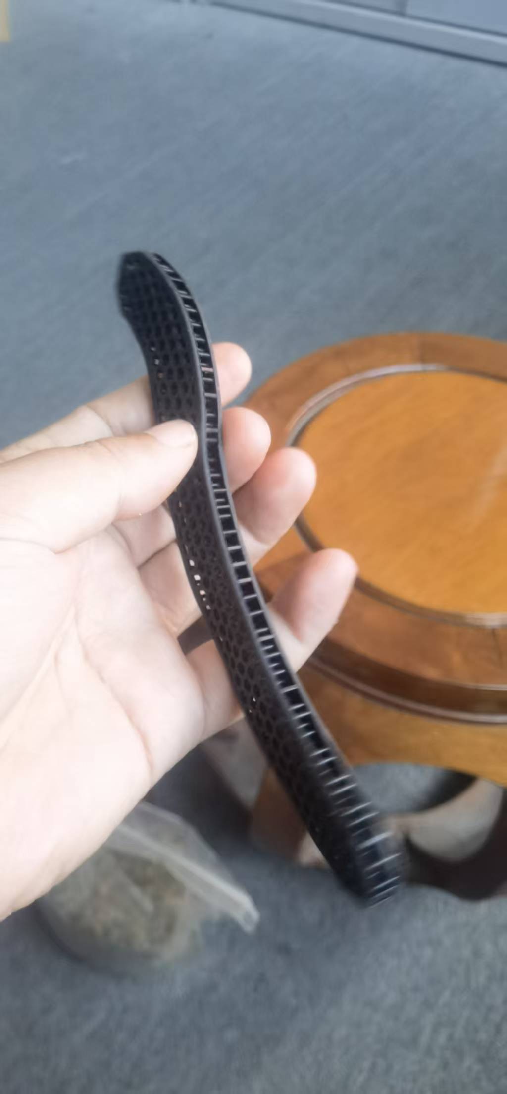
The photo opposite is a cross-section of the hard case: two skin layers joined by internal ribs with a void running between them. In the tool this is a pin standing between two walls, so the cavity is narrow on both sides of it, gas has almost nowhere to go, and the fill front has to wrap around the pin without meeting itself in a cold weld.

These parts are where the process stops being a sheet operation. Fill, venting and cure all have to be solved at the same point in the cavity, and the usual answer is a combination: slower fill, higher mould temperature, vents at the pin seat, and sometimes vacuum.

For the product side — what these pads do in a helmet, insole or seat — see perforated silicone parts.
两层中间镂空
Section through a two-layer pad: skin on both faces, ribs in between, a continuous void running the length of the part.

Gas

Vent where the gas collects, not where it is convenient

In a perforated pad the gas collects in predictable places: at the base of every pin, in the corner where the pin meets the cavity floor, and in the last point of the fill front. Vents belong there — shallow, self-cleaning, and inspected on a schedule. A blocked vent does not announce itself as a vent problem; it shows up as burnt spots and as flash bridging a hole.

When the pin field is dense, vacuum assist is often the cheaper answer than trying to place a vent at every pin, because it evacuates the whole cavity before the silicone arrives.

Release

The pad has to leave the pins without being stretched

Silicone is flexible, so people assume it will peel off anything. On a perforated pad that assumption costs hole size: pulling a part off pins stretches it locally, and the holes come out oval. Draft on the pins, a polished pin surface, and ejection that acts on the rim rather than on the web all matter more than the hardness of the compound.

Ejecting through a thin rib field is worse than ejecting through a solid section: an unbalanced ejector pushes one side first and tears the web. A stripper plate or a peel path that follows the rib direction is usually the fix.

Diagnosis

Six defects and what they tell you

On a perforated part, most faults are visible at the hole. Reading them correctly saves a tool revision.

What you seeWhat it usually meansWhere to look
Holes short-filled or teardrop-shapedGas trapped at the pin base, or the fill front arriving too fast to escapeVenting at the pin seat; vacuum; lower injection speed; mould temperature
Flash bridging a holeWorn or undersized pin, flash gap at the pin seat, excessive cavity pressurePin maintenance schedule; clamp force and shot size
Ragged ring or torn edge around a holeThe part is hanging on the pin as it opensPin draft and polish; ejection timing and balance
Holes oversized or ovalThe pad is being stretched on release; pins running hot or cold against the cavityPin temperature; stripping or peeling direction
Hole size varies across the part or between cavitiesCavity temperature drift, or pin wear on one sideMeasure per cavity; record pin replacement
Warp or waviness across the padUneven wall around the holes, differing cure rates through the webRib layout; mould temperature uniformity

Inspection that catches drift

  • Open area: calculated from hole diameter and pitch, then confirmed on the first sample — it is the number that sets airflow and weight;
  • Hole position: measured to the drawing datum, not just diameters;
  • Rib width: measured on a sectioned part at the narrowest point, because that is where fatigue starts;
  • Flash in holes: checked under magnification at first article, then by sampling on the line;
  • Function, where the pad carries load: compression set and flex fatigue rather than appearance alone;
  • Recorded per cavity: drift shows up in one cavity long before the batch average moves.

When punching is the better route

Being honest about this saves money: a flat gasket with generous round holes, low annual volume, sheet stock already on the shelf and no edge-quality requirement is a punched part. The moment the pad has curvature, a graded pattern, ribs under a certain width, or a skin-contact surface where a sheared edge would be felt, moulding becomes the cheaper total cost.

The related process notes are on molding and tooling and capability overview; wear and fatigue test routes are on R&D and testing.

Have a hole pattern that keeps failing?

Send the drawing and a photo of the fault — pin diameter, rib width and venting are usually enough to say what to change before the next tool revision.

Send your project